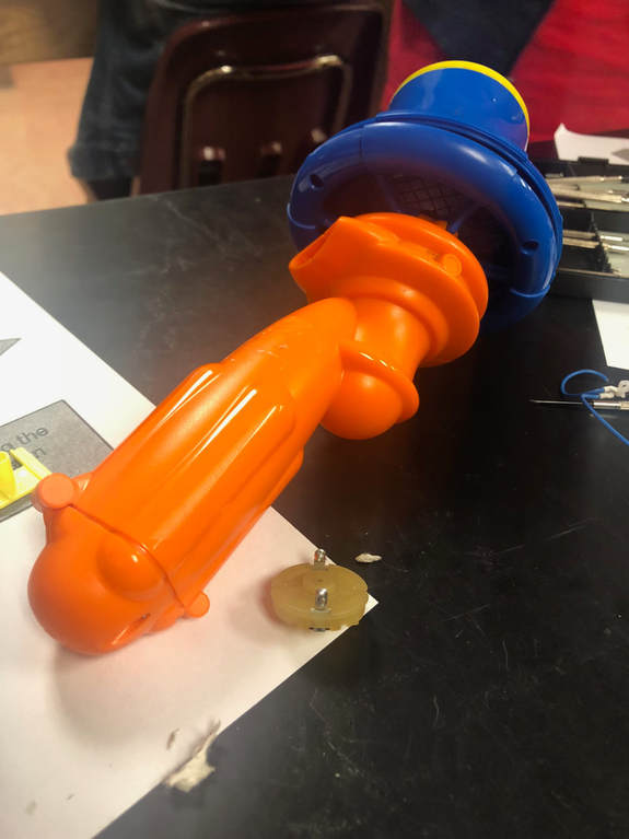
In this project, we deconstructed a toy fan, which we believe was used to keep a ball afloat, We began by sketching the outside of the object, and then began taking it apart using screws. Eventually, we had to use force to pry open the pieces which were glued or soldered together. We then inspected these pieces, and researched what they might be made of, and how they might have been made. A Gantt Chart, logging our work, is linked on the button below.
This project allowed us to examine the actual manufacturing process of an item. By understanding how an item is made, and why it was made that way, we can then think about what we would change about the product. For our group, these changes would be creating better connections between wires, as the product was made for use by small children, but the connections were weak and easily broken. In examining why products are made the way they are, we noticed the strange shape of the handle of our fan. This shape is what made us conclude that the fan was used as a toy, probably to help a ball float.
Below is a link to our presentation.
Below is a link to the Google Doc with our lab write up, which includes pictures of our item. The written piece is also copied below.
Purpose: The purpose of this project was both to help introduce us into the type of resources and information we will need to provide for our final project, and to understand how systems and subsystems work in machines.
Hypothesis: The motor of our fan is built using copper coils and electricity, which allows it to spin.
Hypothesis: The motor of our fan is built using copper coils and electricity, which allows it to spin.
|
Functional Analysis (How parts work together):
List of Components:
|
|
Electricity flows from the batteries, through the wires, to the motor, which, using changing magnetic polarity, causes the metal rod within the motor to spin. The fan attached to the metal rod proceeds to spin; however, the switch blocks the electrical current from completing its circuit. This prohibits the fan from spinning until the switch is pressed down. In order to complete the circuit the the electricity flows through the tin plates at the bottom of the battery housing. The plastic acts as a shell, keeping the electrical components in place, whilst maintaining the structural stability of the product.
Structural Analysis (How the parts connect):
The screws hold the plastic parts together to form the casing of the toy. The motor of the toy is powered by a circuit. The cone springs and battery connectors draw energy from four AA batteries. The springs and connectors alternate touching the positive and negative sides of the batteries. One end of the red positive wire was soldered onto a spring and the other end was soldered on to one of the motor leads. The blue 81mm negative wire is soldered to a spring and one end of the 15mm connector. The second blue wire 61mm is soldered to the other end of the connector and to the second lead of the motor. The connector is the switch that opens and closes the circuits. When the circuit is closed power or current flows through powering the motor to spin the fan. The connector is made from two pieces of metal are not in direct contact.e They In parallel held together by plastic casing on the tip of one end. When the plastic trigger is pushed it pushes against the plastic switch which pushes on one3 of the pieces of metal from the connector onto the other piece of metal completely the circuit.
Material Analysis (materials and properties):
The plastic pieces are made from high-density polyethylene, also known as polyethylene thermoplastic. High-density polyethylene is used in many toys because it is durable, malleable, and resistant. It is also nontoxic, which makes it valuable in food packaging as well as in toys for young children. It is considered to be one of the safest plastics, due to its unreactivity.
The electric motor is made with a rotor coil, armature, commutator, permanent magnets, brushes, and a former. The rotor coil is made with copper because copper is an extremely good conductor of electricity. When electricity flows through the coils, it forms an electromagnet. These coils are wound around the armature, which is made of aluminum. Aluminum is paramagnetic, meaning that it is slightly magnetic, but does not retain a permanent magnetism. The commutator is used to reverse the direction of the electric current each time the coil moves through the plane perpendicular to the magnetic field. This is made of copper. The permanent magnets are most likely made of nickel or iron, as they tend to be cheaper than alloys made from rare-earth metals. Iron and nickel are some of the most common metals used to create ferromagnetic materials, which are materials that maintain a permanent magnetic field. The brushes are made of graphite and copper, as carbon does not wear down as quickly as copper or steal, as it is highly heat resistant. These brushes help to transfer electrical currents to the commutator. The former is made of steel, due to steel’s durability, and holds the permanent magnets in place.
The wiring is made of copper and aluminum, as they are good conductors and are inexpensive. The wires are soldered onto the leads and springs using copper and tin due to their low melting point and malleability. The wire insulation is most likely made of polyvinyl chloride, as it is one of the least expensive and most commonly used thermoplastic for wire insulation.
The screws are most likely made of an aluminum alloy as it is inexpensive and durable.
Manufacturing Analysis (How product was made):
This product was clearly designed in two parts starting with one of the larger orange pieces, which contains many different holes/slots for the other pieces and screws to fit into.
Before the rest of the main construction could continue, the subsystem that involves the motor, fan and fan cover must be assembled. The motor is then slotted into the piece and the fan is put on the other side. Next, the fan housing is put over the fan and screwed into place, completing this system.
The next step of the manufacturing process must have involved attaching the fan system to the rest of the electronic components (battery, battery housing, and switch). This system was then slotted into the original orange handle and covered by the other side of the orange handle. Finally, the two pieces were screwed together to secure the product.
Reflection
In this project, I think our group worked extremely well together. We were all cooperative, and it was amazing working with everyone. I think I did well at working as a team member, rather than trying to do it all myself. Because James and Andre have more computer skills, they took charge of some of the more detailed computer pieces, such as the Gantt Chart. I asked them questions about how to do what they were doing, so I was able to learn. I focused on researching the materials and measuring each item, because I found that I enjoyed learning about the materials of items, as well as why they were made of the materials that they were made of.
I learned that I need to work on staying focused and on task, We could have gone much more in depth into our research if we had used our time more effectively. I struggled with keeping my writing scientific. Because I write poetry, I tend to use flowery, detailed language, which tends not to be scientific. My group really helped me with editing my writing for the lab report.
I learned that I need to work on staying focused and on task, We could have gone much more in depth into our research if we had used our time more effectively. I struggled with keeping my writing scientific. Because I write poetry, I tend to use flowery, detailed language, which tends not to be scientific. My group really helped me with editing my writing for the lab report.
